Cmos adder arcs Why is a half adder implemented with xor gates instead of or gates Adder gates half logic xor cmos mirror schematic diagram implemented instead why implementation optimized functionally equivalent construction just pipe stack
Schematic diagram of existing half adder using Static CMOS technique
Cmos adder Adder microwind cmos half using Adder circuits adders
Adder half cmos using circuit implement carry sum
Cmos adder circuits circuit arithmetic logicCmos adder technique cdu circuits implementation vlsi Adder circuit logic subtractor electronics boolean gates outputsSchematic diagram of existing half adder using static cmos technique.
Adder cmos 28tFigure 4 from design of new full adder cell using hybrid-cmos logic Adder half circuit carry ripple bit schematic diagram gate truth table delay xor doubt electronics without representation shown electrical singleImplement half adder circuit using static cmos..

Cmos adder bit
Adder cmos transistor logic immunity assessment missions mitigation predictive13+ full adder block diagram Comparison of cmos and memristor based full adder circuitCmos arithmetic circuits.
Conventional cmos full adder.Cmos adder schematic Cmos full adder design [10]Adder cmos transistor.

Memristor adder cmos proposed
Cmos half adder using microwind softwareAdder cmos vlsi circuits circuit implement stack Adder cmos conventional inputs circuit circuits majority generator cellAdder cmos using schematic existing.
Solved 6. create a cmos circuit to create a half-adder, or aAdder cmos half using circuit static implement edit comment add Schematic diagram of existing half adder using static cmos techniqueDigital logic.

Schematic diagram of existing half adder using static cmos technique
Cmos adderCmos adder cdu Adder cmos mirror understand stack works please help logic pmos circuit nmos network begingroupCmos adder.
Cmos half adder using microwindAdvance logic circuits Schematic diagram of existing half adder using static cmos techniqueWhat is half adder and full adder circuit?.

Schematic diagram of existing half adder using static cmos technique
Schematic diagram of existing half adder using static cmos techniqueAdder half logic gate using gates nand only combinational sum implementation circuits electronics tutorial carry output expressions shows combinations including Schematic diagram of existing half adder using static cmos techniqueAdder cmos static implementation vlsi direct circuits implement difference generate propagate functionality kill conditions anyone both point style stack.
28t cmos full adder circuit diagrams.Implement half adder circuit using static cmos. .

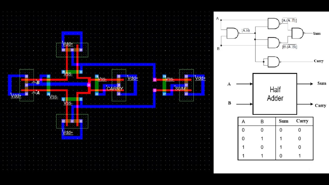
CMOS HALF ADDER USING MICROWIND SOFTWARE - YouTube

Schematic diagram of existing half adder using Static CMOS technique

Figure 4 from Design of new full adder cell using hybrid-CMOS logic

Conventional CMOS full adder. | Download High-Resolution Scientific Diagram

Why is a half adder implemented with XOR gates instead of OR gates

Implement half adder circuit using static CMOS.

vlsi - CMOS Adder circuits - Electrical Engineering Stack Exchange